June 15th, 2019
  Nilesh Chaurasia
 Arduino LED Fade with PWM
Arduino LED Fade Code is used to test the PWM feature of board. Fading mainly uses analogWrite function on Analog Output Pins of Arduino Board.
Arduino does not have DAC (Digital to Analog Converter) capability, but in place of DAC it is having PWM (Pulse Width Modulation) capability. The PWM means, changing the average energy of the signal by varying the width of the pulse.
Some digital I/O pins supports the PWM capability, means all the pins are not able to produce the PWM signals.
The resolution of PWM is of 8 bits, means you can specify the pulse width in numbers from 0 to 255. 0 means 0 width or zero energy, and 255 means maximum width or 100% energy.
Note:The PWM is a way to deliver the average power to some output devices like LED, DC motor etc. It is one of the popular method used to control the speed of DC motor.
PWM Arduino Code
To test the PWM features of the board is really a complex task, and hence we have to write fading code.
Fading means the brightness of the LED is at a minimum level, and then increasing gradually, finally reach to maximum level, and then decreasing gradually. And this continue in the loop for indefinitely.
It means if LED is connected on that PWM pin then you will see a fading effect.
Example 1 – LED fading code on pin number 9.
/*
	Arduino fade an LED using the analogWrite()
	https://elextutorial.com
	The circuit: LED attached from pin 9 to ground in series with resistance of 220 ohm.
*/

int ledPin = 9;    // Specify the LED connection on pin number 9

void setup() {
  // nothing to write here
}

void loop() {

  for (int fadeValue = 0 ; fadeValue <= 255; fadeValue += 5) // Gradually increasing Pulse Width
  {

    analogWrite(ledPin, fadeValue);	// Call of analogWrite function on pin 9 with fadeValue variable

    delay(30);// delay of 30 milliseconds in between next update
  }

  // fade out from max to min in increments of 5 points:
  for (int fadeValue = 255 ; fadeValue >= 0; fadeValue -= 5)  // Gradually decreasing Pulse Width
  {

    analogWrite(ledPin, fadeValue);	// Call of analogWrite function on pin 9 with fadeValue variable

    delay(30);	// delay of 30 milliseconds in between next update
  }
}
In the program we have used analogWrite function to set the PWM level. In the first for loop PWM level is increasing and in the second for loop it is decreasing.
In this example we have generated the PWM signal on the pin number 9, which is one of the PWM pin on the Arduino Uno board.
On the breadboard you have to connect a LED with the pin number 9 in series with resistance of 220 ohm.
Figure 1 below shows the PWM signal example circuit on breadboard. It shows that only pin number 9 need to be connected with LED.
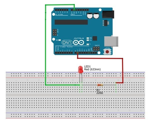
Caution:The pin number 13 does not support the PWM feature in Arduino Uno.
What is PWM
Figure 2 below shows the PWM signal example and the average % energy it contain.
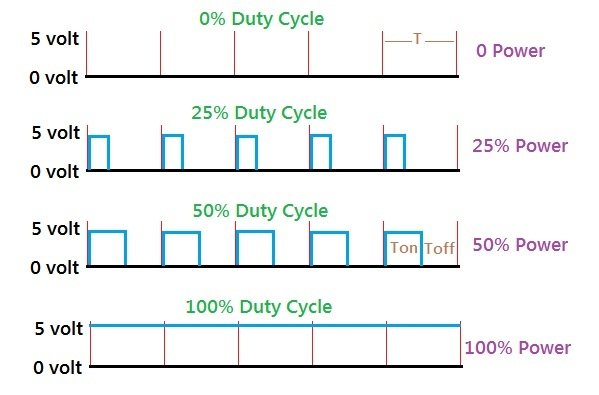
The total pulse time is denoted by T. On time is denoted by Ton and off time is denoted by Toff. The average power is calculated by the ratio Ton / T.
Also it is important to note that ( T = Ton + Toff ).
The total time T depends on the PWM frequency, in Arduino Uno it is approximately 500 Hz.
Arduino Analog Output with analogWrite Function
Arduino library have a function called analogWrite to specify the average % power apply to the analog output pin.
Set pin 9 into analog output mode and set the power to 0 %.
analogWrite(9,0);
Set pin 9 into analog output mode and set the power to 50 %.
analogWrite(9,127);
Set pin 9 into analog output mode and set the power to 100 %.
analogWrite(9,255);
Arduino Uno PWM Pins
It is important to understand that all of the digital pins of Uno does not support the PWM or analogWrite function.
Only digital pins marked with tilde sign ( ~ ) support the PWM feature.
Figure 3 below shows the PWM or analog output pins of the Uno board.

Warning:Only pin number 3, 5, 6, 9, 10 and 11 support the analog output or PWM in Arduino Uno.
 Posted in
  Tags:
Tags: