 June 13th, 2019
  Nilesh Chaurasia
 Arduino LED Blink Code or Project
LED blinking or toggle program is one of the basic practice to test everything working properly. In the blinking program digital pins are on and off continuously with a delay.
Arduino Uno is one of very popular board these days, and it is having a build-in LED on pin number 13. And in this program what we have to do just set pin 13 to on and off with some delay.
Example 1 – Arduino LED Blinking Project Code on pin number 13.
/*
   Blink Program
   https://elextutorial.com
   Turns on LED on and then off for continuously, with delay of one second.
*/

void setup()
{
   pinMode(13, OUTPUT);	// set pin 13 as an output, the pin having onboard LED.
}

void loop()
{
   digitalWrite(13, HIGH); // turn the pin HIGH means on (set)
   delay(1000); // delay for one second
   digitalWrite(13, LOW); // turn the pin LOW means on (reset)
   delay(1000); // delay for one second
}
The structure of Arduino program having two functions one is setup() and other one is loop().
The setup function runs ones when Arduino power on or you can say starts. And the loop function runs again and again, means it behave like an infinite loop.
In the setup function only one statement to set the pin 13 into output mode, with the pinMode function.
In the loop function there are four statements. Set the pin 13, then delay for one second, then reset the pin 13 and then delay again for one second.
Note: The LED on pin number 13 is labeled as “L”. The board may have more LED’s labeled as TX, RX and ON.
How to Control LED in Arduino
To control the LED with Arduino, we have to interface the LED with the digital pin of Arduino. But in Uno pin 13 having build-in LED on board.
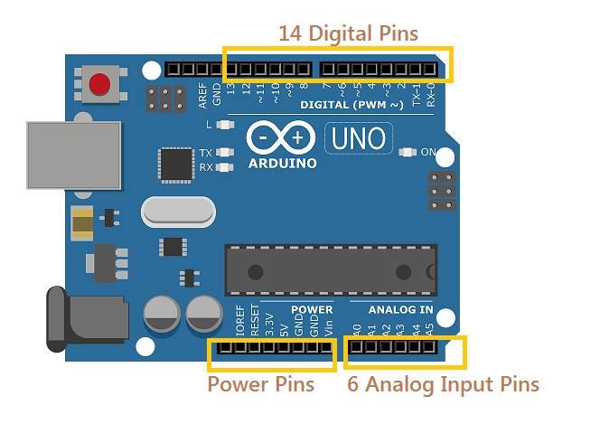
Arduino Uno Digital Pins
In Uno pin 13 having build-in LED on board. Figure 1 shows the Uno board digital pins, it is having 14 digital pins named from pin 0 to pin 13.
Arduino pinMode Function
All the digital pins can be used as input or output in Arduino. And we have to set the pin into output mode with the help of pinMode function.
Set pin 13 into output mode with pinMode Function
pinMode(13,OUTPUT);
Set pin 13 into input mode with pinMode Function
pinMode(13,INPUT);
Arduino Digital Output with digitalWrite Function
All the digital output pins can be set (HIGH or 1) or reset (LOW or 0) in Arduino. And we have to set or reset the pin 13 with the help of digitalWrie function.
Set pin 13 with digitalWrite() Function
digitalWrite(13,HIGH);
Reset pin 13 with digitalWrite() Function
digitalWrite(13,LOW);
Arduino delay Function
delay() function is used to insert delay between two instruction. The number specified in the delay function is in milli seconds.
Delay for five second with delay() Function
delay(5000);
Control LED on other Pins
To control the LED on other I/O pins, you need to interface the LED with the digital pin of Arduino as shown in the figure 2. In this circuit we have connected or interfaced LED with resistance of 220 ohm from pin number 12.
Caution: It is necessary to connect with resistance, you can not connect directly with pin. The value of resistance may be 220 ohm, 330 ohm or 470 ohm. If value of resistance higher the light of LED will be less.

Example 2 – Arduino LED Toggle or Blink Project Code on pin number 12.
/*
   Blink Program 2
   https://elextutorial.com
   Turns on LED on and then off for continuously, with delay of one second on pin 12.
*/

void setup()
{
   pinMode(12, OUTPUT);	// set pin 12 as an output, the pin having onboard LED.
}

void loop()
{
   digitalWrite(12, HIGH); // turn the pin HIGH means on (set)
   delay(1000); // delay for one second
   digitalWrite(12, LOW); // turn the pin LOW means on (reset)
   delay(1000); // delay for one second
}
You can see the difference in the pinMode and digitalWrite function, in place of pin number 13 now it is 12.
 Posted in
  Tags:
Tags: 


It’s really a nice and helpful piece of info. I’m satisfied that you simply shared this useful information with us. Please keep us up to date like this. Thanks for sharing.